Product Description
Product Description
120kw 3 in 1 power assembly (motor + controller
+ reducer) adopts automobile grade IGBT with high
reliability, high integration, high lightweight and small
volume, which can be applied to class A, B, medium
SUV and MPV pure electric vehicles.
Detailed Photos
| Model | battery voltage V |
Rated speed rpm |
Peak Speed rpm |
Rated Power kw |
Peak Power kw |
Back EMF v |
Peak Current A |
Rated Torque N.m |
Peak Torque N.m |
Gearbox Ratio | Cooling Type |
| Powertrain:Motor and controller 2 in one | |||||||||||
| MC6-46-HP | 60 | 2500 | 6000 | 3 | 6 | 10.9 | 190 | 11.5 | 46 | / | natural cooling |
| MC10-75-HP | 72 | 3410 | 7500 | 10 | 20 | 12 | 320 | 28 | 85 | / | natural cooling |
| MC10-60-48-HP | 48 | 3500 | 6500 | 6 | 10 | 11.55 | 295 | 16.4 | 60 | / | natural cooling |
| MC20-80-96-HP | 96 | 4500 | 7500 | 10 | 20 | 12 | 320 | 21 | 85 | / | natural cooling |
| Powertrain:Motor and gearbox 2 in 1 with controller | |||||||||||
| P6-46-HP | 60 | 2500 | 6000 | 3 | 6 | 10.9±0.5 | 190 | 11.5 | 46 | 8.33 | natural cooling |
| P6-46-HP | 72 | 2500 | 6000 | 3 | 6 | 10.9±0.5 | 190 | 11.5 | 46 | 8.33 | natural cooling |
| P8-60-HP48 | 48 | 3000 | 6000 | 4 | 8 | / | 300 | 12.7 | 60 | 7.964 | natural cooling |
| P8-60-HP60 | 60 | 3000 | 6500 | 4 | 8 | / | 300 | 12.7 | 60 | 7.964 | natural cooling |
| P10-75-HP | 60 | 3000 | 7500 | 5 | 10 | 12.5±0.5 | 270 | 16 | 75 | 8.33 | natural cooling |
| P10-75-HP | 72 | 3000 | 7500 | 5 | 10 | 12.5±0.5 | 270 | 16 | 75 | 8.33 | natural cooling |
| P15-100-HP | 60 | 4000 | 7500 | 7.5 | 15 | 12.2±0.5 | 400 | 18 | 100 | 8.33 | natural cooling |
| P20-70-HP | 96 | 5200 | 9300 | 12 | 20 | 9.5 | 350 | 22 | 70 | 8.34 | natural cooling |
| P20-80-HP | 96 | 4500 | 7500 | 10 | 20 | 12 | 320 | 21 | 80 | 8.34 | natural cooling |
| P30-95-JM | 144 | 4500 | 8700 | 15 | 30 | 14 | 320 | 32 | 95 | 8.34 | natural cooling |
| Powertrain: Motor gearbox and controller 3 in one | |||||||||||
| P25-90-HP | 108 | 4500 | 8000 | 15 | 25 | 14 | 320 | 32 | 90 | 8.34 | natural cooling |
| P30-105-HP | 320 | 4500 | 8000 | 15 | 30 | 42 | 120 | 32 | 105 | 8.34 | natural cooling |
| P30-95-HP | 144 | 4500 | 8700 | 15 | 30 | 14 | 320 | 32 | 95 | 8.34 | natural cooling |
| P25-95-108-HP | 108 | 4775 | 8000 | 14 | 25 | 12.6 | 400 | 26 | 95 | 8.34 | natural cooling |
| P25-100-144-HP | 144 | 4775 | 8000 | 13 | 25 | 12.6 | 370 | 26 | 100 | 8.34 | natural cooling |
| P30-105-320-FHP | 320 | 4500 | 7700 | 15 | 30 | 42 | 120 | 32 | 105 | 8.34 | Controller with fan |
| P35-100-144-HP | 144 | 4500 | 8700 | 15 | 35 | 14 | 350 | 32 | 100 | 8.34 | water cooling |
| P45-120-HP | 320 | 4050 | 12000 | 20 | 45 | 24.5 | 235 | 47 | 120 | 10.3 | water cooling |
| P70-165-JL | 336 | 4050 | 12000 | 30 | 70 | 32.85 | 255 | 70 | 165 | 10.5 | water cooling |
| P100-220-HP | 360 | 5000 | 14000 | 50 | 100 | 31.6 | 355 | 95.5 | 220 | 10 | water cooling |
| P120-260-HP | 360 | 5000 | 14000 | 60 | 120 | 28.5 | 460 | 114 | 260 | 10 | water cooling |
Company Profile
XIHU (WEST LAKE) DIS. POWER master 3 core technologies of electric vehicle power assembly: motor, electric control and reducer; and XIHU (WEST LAKE) DIS. POWER has a global vision, adopts international advanced management concept, integrates R & D, manufacturing, sales and service, and provides customers with low-speed, high torque, high integration, high-speed and low noise, strong overload capacity, high protection level, system maintenance free The shape is exquisite and beautiful, the protection function is complete, the vector control and various prameters can be adjusted according to the customer requirements.
Xihu (West Lake) Dis. Power Co.,Ltd. was founded in March,2571. It is a national Hi-Tech enterprise which specialized in providing energy-saving system.
Xihu (West Lake) Dis. Power Co., Ltd. consists of Xihu (West Lake) Dis. Power (ZheJiang ) Co., Ltd., Xihu (West Lake) Dis. Power (ZheJiang ) Co., Ltd., and Xihu (West Lake) Dis. Power (HangZhou) Co., Ltd. The headquarters is located at No. 26, Yingbin Avenue, National High-tech Zone, HangZhou, ZheJiang . The company can annually produce 250,000 electric vehicle powertrains, 300,000 electric vehicle motors, and 300,000 controllers.
Xihu (West Lake) Dis. Power has a high-quality technical R&D team of more than 120 people, with high-tech talents selected from the National Ten Thousand Talents Program, National Science and Technology Innovation and Entrepreneurship Talents, ZheJiang Science and Technology Entrepreneurship Leaders, Xihu (West Lake) Dis.ang Top Talents, and Xihu (West Lake) Dis.ang Scarce Talents. And independently developed electric vehicle powertrains, permanent magnet synchronous motors, AC asynchronous motors, permanent magnet synchronous controllers, AC asynchronous controllers and other products, serving electric passenger cars, electric logistics vehicles, electric buses, electric minibuses, New energy vehicle industries such as electric forklifts, electric engineering vehicles, and electric logistics vehicles. Xihu (West Lake) Dis. Power has mastered the core technologies of electric vehicle motors, controllers, reducers and powertrains, established the ZheJiang Engineering Technology R&D Center, and listed the ZheJiang Provincial Key Laboratory, with more than 120 sets of experimental benches and experimental equipment. Design and development, performance verification, durability test, IP67 waterproof and dustproof test, mechanical vibration test, mechanical shock test, and full working conditions NVH experiment, high and low temperature cyclic impact experiment, high and low temperature loading operation experiment and other product design verification and testing capabilities.
Xihu (West Lake) Dis. Power has built an electric vehicle powertrain automated assembly workshop, an electric motor automated assembly workshop, a controller CHINAMFG automatic placement workshop, an automated winding and embedding workshop, a casting processing center, an online spraying center, a complete machine performance digital inspection center, and Created a zero-defect quality assurance system to provide customers with perfect products and high-quality services. Xihu (West Lake) Dis. Power has obtained the automotive industry IATF16949:2016 quality management system certification, ISO9001:2015 quality management system certification, ISO14001:2015 environmental management system certification, ISO45001:2018 occupational health and safety management system certification, EU product safety CE certification, and U.S. product safety Performance UL certification, Korean electrical product safety KC certification, etc.
At present, the company has formed a research and development platform suitable for 6 categories of electric drive products such as pure electric passenger vehicles, pure electric commercial vehicles, pure electric special vehicles, extended-range hybrids, electric vehicles, and intelligent unmanned vehicles, forming a 1.2kw- 500kw power series products, supporting the development of more than 260 varieties of electric power system products for domestic and foreign vehicle companies and power system integrators. In terms of application in the electric vehicle market, the company’s products are used in electric vehicles such as FIAT, Xpeng, BAIC, Geely, BYD, Changan, Xihu (West Lake) Dis.feng, Xihu (West Lake) Dis., Haima, Zotye, GM, King Long, Xihu (West Lake) Dis., Foton, Great Wall, Weimar and other electric vehicles. It has been successfully applied and has been among the best in market share for many years. The company’s products sell well all over the country, and are exported to Europe, America, India, the Middle East, Africa and Southeast Asia.
Xihu (West Lake) Dis. Power, Innovation Technology!
Certifications
FAQ
Q1. What are your terms of packing?
A: We pack our goods in neutral wooden boxes and paper cartons. If you have a legally registered brand, we can pack the goods in your branded boxes after getting your authorization letters.
Q2. What are your terms of payment?
A: T/T 30% as deposit, and 70% before delivery. We’ll send you the photos of the products and packages before you pay the balance. For big orders, we accept L/C.
Q3. What are your terms of delivery?
A: EXW, FOB.
Q4. How about your delivery time?
A: It will take 15 to 45days after receiving your advance payment. The specific delivery time depends on the items and the quantity of your order.
Q5. Can you produce according to the samples?
A: Yes, we can produce your samples or technical drawings. We can produce the molds and fixtures in-house.
Q6. Do you test all your goods before delivery?
A: Yes, we have a 100% test before delivery, if necessary we can send an inspection report before delivery.
Q7. How long is your warranty period?
A: In general,2 years after deliveried
Q8. Do you have any certificates?
A: CE,SGS,ISO9001,IATF16949,UL,Etc
Q9. Do you have the import & export license?
We are official import & export licensed manufacturer.
/* March 10, 2571 17:59:20 */!function(){function s(e,r){var a,o={};try{e&&e.split(“,”).forEach(function(e,t){e&&(a=e.match(/(.*?):(.*)$/))&&1
| Application: | Universal, Industrial, Power Tools, Car |
|---|---|
| Operating Speed: | High Speed |
| Operation Mode: | Electric Motor |
| Magnetic Structure: | Permanent Magnet |
| Function: | Driving |
| Structure: | Rotating Pole Type (Armature Fixed) |
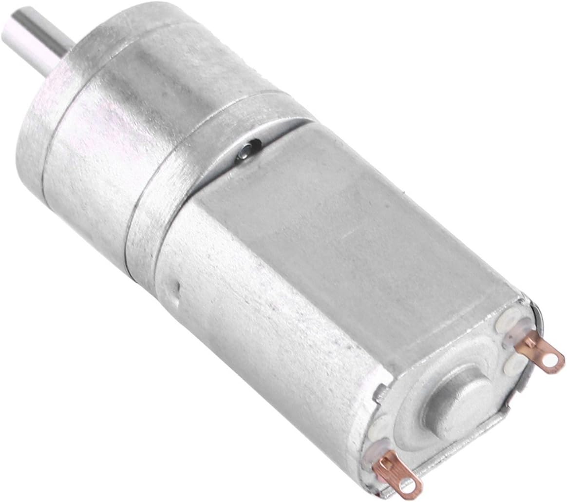
What types of feedback mechanisms are commonly integrated into gear motors for control?
Gear motors often incorporate feedback mechanisms to provide control and improve their performance. These feedback mechanisms enable the motor to monitor and adjust its operation based on various parameters. Here are some commonly integrated feedback mechanisms in gear motors:
1. Encoder Feedback:
An encoder is a device that provides position and speed feedback by converting the motor’s mechanical motion into electrical signals. Encoders commonly used in gear motors include:
- Incremental Encoders: These encoders provide information about the motor’s shaft position and speed relative to a reference point. They generate pulses as the motor rotates, allowing precise measurement of position and speed changes.
- Absolute Encoders: Absolute encoders provide the precise position of the motor’s shaft within a full revolution. They do not require a reference point and provide accurate feedback even after power loss or motor restart.
2. Hall Effect Sensors:
Hall effect sensors use the principle of the Hall effect to detect the presence and strength of a magnetic field. They are commonly used in gear motors for speed and position sensing. Hall effect sensors provide feedback by detecting changes in the motor’s magnetic field and converting them into electrical signals.
3. Current Sensors:
Current sensors monitor the electrical current flowing through the motor’s windings. By measuring the current, these sensors provide feedback regarding the motor’s torque, load conditions, and power consumption. Current sensors are essential for motor control strategies such as current limiting, overcurrent protection, and closed-loop control.
4. Temperature Sensors:
Temperature sensors are integrated into gear motors to monitor the motor’s temperature. They provide feedback on the motor’s thermal conditions, allowing the control system to adjust the motor’s operation to prevent overheating. Temperature sensors are crucial for ensuring the motor’s reliability and preventing damage due to excessive heat.
5. Hall Effect Limit Switches:
Hall effect limit switches are used to detect the presence or absence of a magnetic field within a specific range. They are commonly employed as end-of-travel or limit switches in gear motors. Hall effect limit switches provide feedback to the control system, indicating when the motor has reached a specific position or when it has moved beyond the allowed range.
6. Resolver Feedback:
A resolver is an electromagnetic device used to determine the position and speed of a rotating shaft. It provides feedback by generating sine and cosine signals that correspond to the shaft’s angular position. Resolver feedback is commonly used in high-performance gear motors requiring accurate position and speed control.
These feedback mechanisms, when integrated into gear motors, enable precise control, monitoring, and adjustment of various motor parameters. By utilizing feedback signals from encoders, Hall effect sensors, current sensors, temperature sensors, limit switches, or resolvers, the control system can optimize the motor’s performance, ensure accurate positioning, maintain speed control, and protect the motor from excessive loads or overheating.
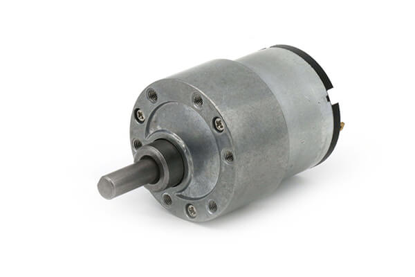
Can gear motors be used for precise positioning, and if so, what features enable this?
Yes, gear motors can be used for precise positioning in various applications. The combination of gear mechanisms and motor control features enables gear motors to achieve accurate and repeatable positioning. Here’s a detailed explanation of the features that enable gear motors to be used for precise positioning:
1. Gear Reduction:
One of the key features of gear motors is their ability to provide gear reduction. Gear reduction refers to the process of reducing the output speed of the motor while increasing the torque. By using the appropriate gear ratio, gear motors can achieve finer control over the rotational movement, allowing for more precise positioning. The gear reduction mechanism enables the motor to rotate at a slower speed while maintaining higher torque, resulting in improved accuracy and control.
2. High Resolution Encoders:
Many gear motors are equipped with high-resolution encoders. An encoder is a device that measures the position and speed of the motor shaft. High-resolution encoders provide precise feedback on the motor’s rotational position, allowing for accurate position control. The encoder signals are used in conjunction with motor control algorithms to ensure precise positioning by monitoring and adjusting the motor’s movement in real-time. The use of high-resolution encoders greatly enhances the gear motor’s ability to achieve precise and repeatable positioning.
3. Closed-Loop Control:
Gear motors with closed-loop control systems offer enhanced positioning capabilities. Closed-loop control involves continuously comparing the actual motor position (as measured by the encoder) with the desired position and making adjustments to minimize any position error. The closed-loop control system uses feedback from the encoder to adjust the motor’s speed, direction, and torque, ensuring accurate positioning even in the presence of external disturbances or variations in the load. Closed-loop control enables gear motors to actively correct for position errors and maintain precise positioning over time.
4. Stepper Motors:
Stepper motors are a type of gear motor that provides excellent precision and control for positioning applications. Stepper motors operate by converting electrical pulses into incremental steps of movement. Each step corresponds to a specific angular displacement, allowing precise positioning control. Stepper motors offer high step resolution, allowing for fine position adjustments. They are commonly used in applications that require precise positioning, such as robotics, 3D printers, and CNC machines.
5. Servo Motors:
Servo motors are another type of gear motor that excels in precise positioning tasks. Servo motors combine a motor, a feedback device (such as an encoder), and a closed-loop control system. They offer high torque, high speed, and excellent positional accuracy. Servo motors are capable of dynamically adjusting their speed and torque to maintain the desired position accurately. They are widely used in applications that require precise and responsive positioning, such as industrial automation, robotics, and camera pan-tilt systems.
6. Motion Control Algorithms:
Advanced motion control algorithms play a crucial role in enabling gear motors to achieve precise positioning. These algorithms, implemented in motor control systems or dedicated motion controllers, optimize the motor’s behavior to ensure accurate positioning. They take into account factors such as acceleration, deceleration, velocity profiling, and jerk control to achieve smooth and precise movements. Motion control algorithms enhance the gear motor’s ability to start, stop, and position accurately, reducing position errors and overshoot.
By leveraging gear reduction, high-resolution encoders, closed-loop control, stepper motors, servo motors, and motion control algorithms, gear motors can be effectively used for precise positioning in various applications. These features enable gear motors to achieve accurate and repeatable positioning, making them suitable for tasks that require precise control and reliable positioning performance.
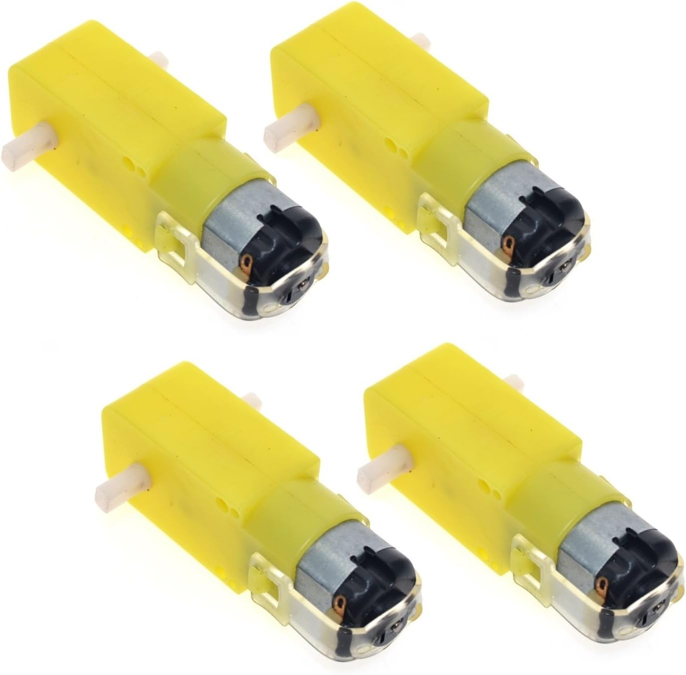
What is a gear motor, and how does it combine the functions of gears and a motor?
A gear motor is a type of motor that incorporates gears into its design to combine the functions of gears and a motor. It consists of a motor, which provides the mechanical power, and a set of gears, which transmit and modify this power to achieve specific output characteristics. Here’s a detailed explanation of what a gear motor is and how it combines the functions of gears and a motor:
A gear motor typically consists of two main components: the motor and the gear system. The motor is responsible for converting electrical energy into mechanical energy, generating rotational motion. The gear system, on the other hand, consists of multiple gears with different sizes and tooth configurations. These gears are meshed together in a specific arrangement to transmit and modify the output torque and speed of the motor.
The gears in a gear motor serve several functions:
1. Torque Amplification:
One of the primary functions of the gear system in a gear motor is to amplify the torque output of the motor. By using gears with different sizes, the input torque can be effectively multiplied or reduced. This allows the gear motor to provide higher torque at lower speeds or lower torque at higher speeds, depending on the gear arrangement. This torque amplification is beneficial in applications where high torque is required, such as in heavy machinery or vehicles.
2. Speed Reduction or Increase:
The gear system in a gear motor can also be used to reduce or increase the rotational speed of the motor output. By utilizing gears with different numbers of teeth, the gear ratio can be adjusted to achieve the desired speed output. For example, a gear motor with a higher gear ratio will output lower speed but higher torque, whereas a gear motor with a lower gear ratio will output higher speed but lower torque. This speed control capability allows for precise matching of motor output to the requirements of specific applications.
3. Directional Control:
Gears in a gear motor can be used to control the direction of rotation of the motor output shaft. By employing different combinations of gears, such as spur gears, bevel gears, or worm gears, the rotational direction can be changed. This directional control is crucial in applications where bidirectional movement is required, such as in conveyor systems or robotic arms.
4. Load Distribution:
The gear system in a gear motor helps distribute the load evenly across multiple gears, which reduces the stress on individual gears and increases the overall durability and lifespan of the motor. By sharing the load among multiple gears, the gear motor can handle higher torque applications without putting excessive strain on any particular gear. This load distribution capability is especially important in heavy-duty applications that require continuous operation under demanding conditions.
By combining the functions of gears and a motor, gear motors offer several advantages. They provide torque amplification, speed control, directional control, and load distribution capabilities, making them suitable for various applications that require precise and controlled mechanical power. Gear motors are commonly used in industries such as robotics, automotive, manufacturing, and automation, where reliable and efficient power transmission is essential.


editor by CX 2024-02-16