Product Description
hydraulic gear motor type flow divider with relief valve
Two or several gear motors can be combined to flow divider after being connected by coupling.It guarantees synchronous operation and accuracy of power element like cylinder.Its principle is as follows,hydraulic liquid from the pipe is input into the inlet port and the same amount liquid is distributed to the outlet port by the rotation of gears that with same specification.
Gear motor flow divider can be integrated with relief valve,check valve and governor valve,protecting system pressure and filling the oil. For specific requirements,pls contact we GRH.
Product Description
| Displacement | Minimum Flow/sec | Maximum Flow/sec | |
| in3 | cm3 | GPM | GPM |
| 0.097 | 1.6 | 0.8 | 1.7 |
| 0.129 | 2.13 | 1.2 | 2.5 |
| 0.194 | 3.18 | 1.7 | 4.5 |
| 0.258 | 4.24 | 2.5 | 5.0 |
| 0.323 | 5.29 | 3.0 | 6.0 |
| 0.388 | 6.36 | 3.5 | 7.0 |
| 0.453 | 7.42 | 4.0 | 8.0 |
| 0.517 | 8.42 | 4.5 | 9.0 |
| Displacement | Minimum Flow/sec | Maximum Flow/sec | |
| in3 | cm3 | GPM | GPM |
| 0.366 | 6 | 1.0 | 4.8 |
| 0.488 | 8 | 1.5 | 5.8 |
| 0.671 | 11 | 1.8 | 7.1 |
| 0.854 | 14 | 2.0 | 9.0 |
| 1.037 | 17 | 2.5 | 9.8 |
| 1.525 | 25 | 3.5 | 14.0 |
| 1.891 | 31 | 4.0 | 18.5 |
Company Information
ZheJiang CHINAMFG Hydraulic Technology Co., Ltd
With world class manufacturing facilities, expertise and manufactures in the fluid power industry for over 30 years;
ZheJiang office set in CHINAMFG Building Xihu (West Lake) Dis. District, ZheJiang
Factory set in ZheJiang City, ZheJiang Provience. Four hours driving from ZheJiang .
Our Services
1.Each item tested before delivery;
2.1 year warranty;
3.GRH R&D department: full technician support;
4.GRH quality department: Your feedback help us perform better.
5.Certificate
6.Exhibition
FAQ
| Q: What is our main application? | A: 1.Hydraulic system; 2.Agriculture machine; 3.Constraction machine; 4. Automobile: 5.Local distributors |
| Q:What is our main products? | A: Gear pump / Gear motor / Orbit motor / Flow divider / Monoblock control valve / Log splitter pump & valve / Hydraulic power unit |
| Q: What Is The Payment Terms. | A: Full order: 30% as deposit, the balance before shipment; Small order /sample order: full payment in advance; |
| Q: Can I Mark My Own Brand On The Pump? | A: Yes. Full order could mark your logo and code; |
| Q: What is our main export market? | A: America(45.5%):The United States, Canada, Brazil; Europe(30.8%):Italy,Germany,England,Holland,Spain,Poland. Asia(18.5%):Korea,India,Turkey,Iran, Syria, Israel; Others(5.8%): |
/* January 22, 2571 19:08:37 */!function(){function s(e,r){var a,o={};try{e&&e.split(“,”).forEach(function(e,t){e&&(a=e.match(/(.*?):(.*)$/))&&1
| Drive: | Hydraulic |
|---|---|
| Type: | Hydraulic Motor |
| Name: | Gear Motor Type Flow Divider with Relief Valve |
| Relief Pressure: | 200bar |
| Flow: | 20lpm |
| Usage: | Simultaneous Flow Divider System |
| Customization: |
Available
|
|
|---|
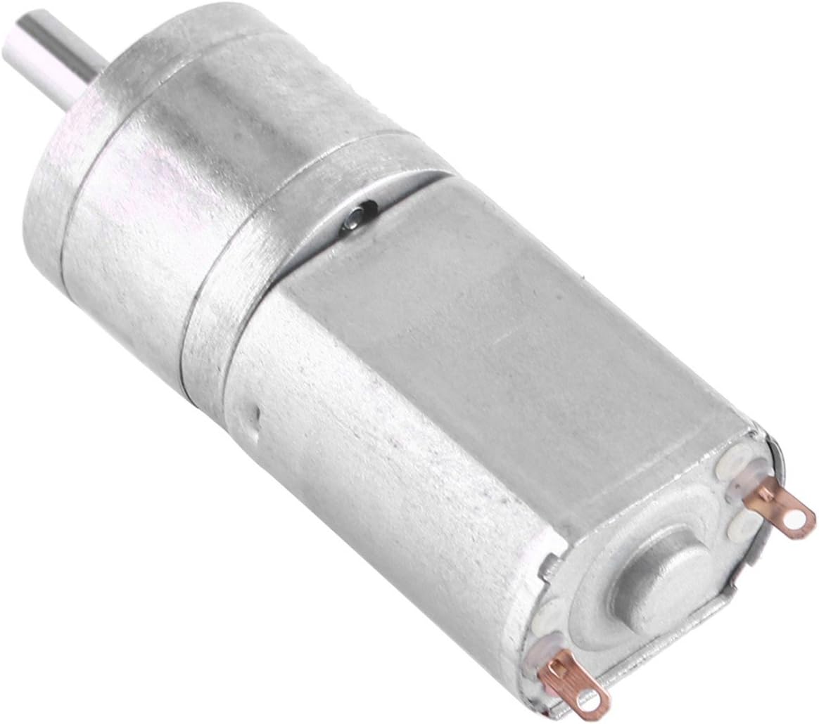
What types of feedback mechanisms are commonly integrated into gear motors for control?
Gear motors often incorporate feedback mechanisms to provide control and improve their performance. These feedback mechanisms enable the motor to monitor and adjust its operation based on various parameters. Here are some commonly integrated feedback mechanisms in gear motors:
1. Encoder Feedback:
An encoder is a device that provides position and speed feedback by converting the motor’s mechanical motion into electrical signals. Encoders commonly used in gear motors include:
- Incremental Encoders: These encoders provide information about the motor’s shaft position and speed relative to a reference point. They generate pulses as the motor rotates, allowing precise measurement of position and speed changes.
- Absolute Encoders: Absolute encoders provide the precise position of the motor’s shaft within a full revolution. They do not require a reference point and provide accurate feedback even after power loss or motor restart.
2. Hall Effect Sensors:
Hall effect sensors use the principle of the Hall effect to detect the presence and strength of a magnetic field. They are commonly used in gear motors for speed and position sensing. Hall effect sensors provide feedback by detecting changes in the motor’s magnetic field and converting them into electrical signals.
3. Current Sensors:
Current sensors monitor the electrical current flowing through the motor’s windings. By measuring the current, these sensors provide feedback regarding the motor’s torque, load conditions, and power consumption. Current sensors are essential for motor control strategies such as current limiting, overcurrent protection, and closed-loop control.
4. Temperature Sensors:
Temperature sensors are integrated into gear motors to monitor the motor’s temperature. They provide feedback on the motor’s thermal conditions, allowing the control system to adjust the motor’s operation to prevent overheating. Temperature sensors are crucial for ensuring the motor’s reliability and preventing damage due to excessive heat.
5. Hall Effect Limit Switches:
Hall effect limit switches are used to detect the presence or absence of a magnetic field within a specific range. They are commonly employed as end-of-travel or limit switches in gear motors. Hall effect limit switches provide feedback to the control system, indicating when the motor has reached a specific position or when it has moved beyond the allowed range.
6. Resolver Feedback:
A resolver is an electromagnetic device used to determine the position and speed of a rotating shaft. It provides feedback by generating sine and cosine signals that correspond to the shaft’s angular position. Resolver feedback is commonly used in high-performance gear motors requiring accurate position and speed control.
These feedback mechanisms, when integrated into gear motors, enable precise control, monitoring, and adjustment of various motor parameters. By utilizing feedback signals from encoders, Hall effect sensors, current sensors, temperature sensors, limit switches, or resolvers, the control system can optimize the motor’s performance, ensure accurate positioning, maintain speed control, and protect the motor from excessive loads or overheating.
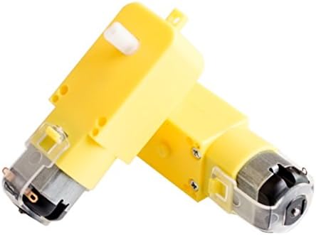
Can you explain the role of backlash in gear motors and how it’s managed in design?
Backlash plays a significant role in gear motors and is an important consideration in their design and operation. Backlash refers to the slight clearance or play between the teeth of gears in a gear system. It affects the precision, accuracy, and responsiveness of the gear motor. Here’s an explanation of the role of backlash in gear motors and how it is managed in design:
1. Role of Backlash:
Backlash in gear motors can have both positive and negative effects:
- Compensation for Misalignment: Backlash can help compensate for minor misalignments between gears, shafts, or the load. It allows a small amount of movement before engaging the next set of teeth, reducing the risk of damage due to misalignment. This can be particularly beneficial in applications where precise alignment is challenging or subject to variations.
- Negative Impact on Accuracy and Responsiveness: Backlash can introduce a delay or “dead zone” in the motion transmission. When changing the direction of rotation or reversing the load, the gear teeth must first overcome the clearance or play before engaging in the opposite direction. This delay can reduce the overall accuracy, responsiveness, and repeatability of the gear motor, especially in applications that require precise positioning or rapid changes in direction or speed.
2. Managing Backlash in Design:
Designers employ various techniques to manage and minimize backlash in gear motors:
- Tight Manufacturing Tolerances: Proper manufacturing techniques and tight tolerances can help minimize backlash. Precision machining and quality control during the production of gears and gear components ensure closer tolerances, reducing the amount of play between gear teeth.
- Preload or Pre-tensioning: Applying a preload or pre-tensioning force to the gear system can help reduce backlash. This technique involves introducing an initial force or tension that eliminates the clearance between gear teeth. It ensures immediate contact and engagement of the gear teeth, minimizing the dead zone and improving the overall responsiveness and accuracy of the gear motor.
- Anti-Backlash Gears: Anti-backlash gears are designed specifically to minimize or eliminate backlash. They typically feature modifications to the gear tooth profile, such as modified tooth shapes or special tooth arrangements, to reduce clearance. Anti-backlash gears can be used in gear motor designs to improve precision and minimize the effects of backlash.
- Backlash Compensation: In some cases, backlash compensation techniques can be employed. These techniques involve monitoring the position or movement of the load and applying control algorithms to compensate for the backlash. By accounting for the clearance and adjusting the control signals accordingly, the effects of backlash can be mitigated, improving accuracy and responsiveness.
3. Application-Specific Considerations:
The management of backlash in gear motors should be tailored to the specific application requirements:
- Positioning Accuracy: Applications that require precise positioning, such as robotics or CNC machines, may require tighter backlash control to ensure accurate and repeatable movements.
- Dynamic Response: Applications that involve rapid changes in direction or speed, such as high-speed automation or servo control systems, may require reduced backlash to maintain responsiveness and minimize overshoot or lag.
- Load Characteristics: The nature of the load and its impact on the gear system should be considered. Heavy loads or applications with significant inertial forces may require additional backlash management techniques to maintain stability and accuracy.
In summary, backlash in gear motors can affect precision, accuracy, and responsiveness. While it can compensate for misalignments, backlash may introduce delays and reduce the overall performance of the gear motor. Designers manage backlash through tight manufacturing tolerances, preload techniques, anti-backlash gears, and backlash compensation methods. The management of backlash depends on the specific application requirements, considering factors such as positioning accuracy, dynamic response, and load characteristics.
Are there specific considerations for selecting the right gear motor for a particular application?
When selecting a gear motor for a specific application, several considerations need to be taken into account. The choice of the right gear motor is crucial to ensure optimal performance, efficiency, and reliability. Here’s a detailed explanation of the specific considerations for selecting the right gear motor for a particular application:
1. Torque Requirement:
The torque requirement of the application is a critical factor in gear motor selection. Determine the maximum torque that the gear motor needs to deliver to perform the required tasks. Consider both the starting torque (the torque required to initiate motion) and the operating torque (the torque required to sustain motion). Select a gear motor that can provide adequate torque to handle the load requirements of the application. It’s important to account for any potential torque spikes or variations during operation.
2. Speed Requirement:
Consider the desired speed range or specific speed requirements of the application. Determine the rotational speed (in RPM) that the gear motor needs to achieve to meet the application’s performance criteria. Select a gear motor with a suitable gear ratio that can achieve the desired speed at the output shaft. Ensure that the gear motor can maintain the required speed consistently and accurately throughout the operation.
3. Duty Cycle:
Evaluate the duty cycle of the application, which refers to the ratio of operating time to rest or idle time. Consider whether the application requires continuous operation or intermittent operation. Determine the duty cycle’s impact on the gear motor, including factors such as heat generation, cooling requirements, and potential wear and tear. Select a gear motor that is designed to handle the expected duty cycle and ensure long-term reliability and durability.
4. Environmental Factors:
Take into account the environmental conditions in which the gear motor will operate. Consider factors such as temperature extremes, humidity, dust, vibrations, and exposure to chemicals or corrosive substances. Choose a gear motor that is specifically designed to withstand and perform optimally under the anticipated environmental conditions. This may involve selecting gear motors with appropriate sealing, protective coatings, or materials that can resist corrosion and withstand harsh environments.
5. Efficiency and Power Requirements:
Consider the desired efficiency and power consumption of the gear motor. Evaluate the power supply available for the application and select a gear motor that operates within the specified voltage and current ranges. Assess the gear motor’s efficiency to ensure that it maximizes power transmission and minimizes wasted energy. Choosing an efficient gear motor can contribute to cost savings and reduced environmental impact.
6. Physical Constraints:
Assess the physical constraints of the application, including space limitations, mounting options, and integration requirements. Consider the size, dimensions, and weight of the gear motor to ensure it can be accommodated within the available space. Evaluate the mounting options and compatibility with the application’s mechanical structure. Additionally, consider any specific integration requirements, such as shaft dimensions, connectors, or interfaces that need to align with the application’s design.
7. Noise and Vibration:
Depending on the application, noise and vibration levels may be critical factors. Evaluate the acceptable noise and vibration levels for the application’s environment and operation. Choose a gear motor that is designed to minimize noise and vibration, such as those with helical gears or precision engineering. This is particularly important in applications that require quiet operation or where excessive noise and vibration may cause issues or discomfort.
By considering these specific factors when selecting a gear motor for a particular application, you can ensure that the chosen gear motor meets the performance requirements, operates efficiently, and provides reliable and consistent power transmission. It’s important to consult with gear motor manufacturers or experts to determine the most suitable gear motor based on the specific application’s needs.


editor by CX 2024-02-29