Product Description
BLDC Series 10490 Brushless DC Gear Motor
Motor Specification
90 MOTOR DATA
| Type | Voltage V | Rated Power W | Rated Torque N.m | No-load Speed RPM | No-load Current A | Rated Speed RPM | Length mm |
| GSBLD90S100D24 | 24 | 100 | 0.478 | 2700 | <0.6 | 2000 | 75 |
| GSBLD90S100D310 | 310 | 100 | 0.478 | 2600 | <0.4 | 2000 | 75 |
| GSBLD90S200D24 | 24 | 200 | 0.955 | 2700 | <0.8 | 2000 | 90 |
| GSBLD90S200D310 | 310 | 200 | 0.955 | 2600 | <0.6 | 2000 | 90 |
| GSBLD90S400D24 | 24 | 400 | 1.91 | 2700 | <1.8 | 2000 | 105 |
| GSBLD90S400D310 | 310 | 400 | 1.91 | 2600 | <1.2 | 2000 | 105 |
DIMENSIONAL DRAWING
104 GEAR BOX
| Gear Ratio | 3 | 3.6 | 5 | 6 | 7.5 | 9 | 10 | 12.5 | 15 | 18 | 20 | 25 | 30 | 36 | 50 | 60 | 75 | 90 | 100 | 120 | 150 |
| Output Speed r/min | 667 | 556 | 400 | 333 | 267 | 222 | 200 | 160 | 133 | 111 | 100 | 80 | 67 | 56 | 40 | 33 | 27 | 22 | 20 | 17 | 13 |
| Allowance Torque Nm | 2.06 | 2.48 | 3.44 | 4.13 | 5.16 | 6.19 | 6.19 | 7.75 | 9.30 | 11.2 | 11.2 | 14.0 | 16.8 | 20.0 | 28.0 | 33.6 | 39.2 | 39.2 | 39.2 | 39.2 | 39.2 |
DIMENSIONAL DRAWING
FAQ
1 Q: What’s your MOQ?
A: 1unit is ok for different types.
2 Q: What about your warranty?
A: One year.
3 Q: Do you provide OEM service with customer-logo?
A: Yes, we could do OEM orders, but we mainly focus on our own brand.
4 Q: How about your payment terms ?
A: TT, western union and paypal. 100% payment in advanced for orders less $5,000. 30% deposit and balance before delivery for orders over $5,000.
5 Q: How about your packing ?
A: Carton, Plywood case. If you need more, we can pack all goods with pallet
6 Q: What information should be given, if I buy from you ?
A: Rated power, gearbox ratio, input speed, mounting position. More details, better!
7 Q: How do you deliver the order?
A: We will compare and choose the most suitable ways of delivery by sea, air or express courier.
Warmly welcome your inquiries !
/* January 22, 2571 19:08:37 */!function(){function s(e,r){var a,o={};try{e&&e.split(“,”).forEach(function(e,t){e&&(a=e.match(/(.*?):(.*)$/))&&1
| Application: | Universal, Industrial, Household Appliances, Car, Power Tools, Appliances |
|---|---|
| Operating Speed: | Low Speed |
| Excitation Mode: | Excited |
| Function: | Driving |
| Casing Protection: | Protection Type |
| Number of Poles: | 4 |
| Samples: |
US$ 20/Piece
1 Piece(Min.Order) | |
|---|
| Customization: |
Available
|
|
|---|
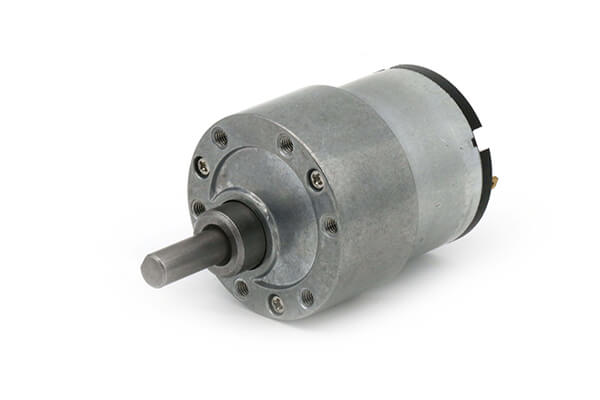
Can gear motors be used in robotics, and if so, what are some notable applications?
Yes, gear motors are widely used in robotics due to their ability to provide torque, precise control, and compact size. They play a crucial role in various robotic applications, enabling the movement, manipulation, and control of robotic systems. Here are some notable applications of gear motors in robotics:
1. Robotic Arm Manipulation:
Gear motors are commonly used in robotic arms to provide precise and controlled movement. They enable the articulation of the arm’s joints, allowing the robot to reach different positions and orientations. Gear motors with high torque capabilities are essential for lifting, rotating, and manipulating objects with varying weights and sizes.
2. Mobile Robots:
Gear motors are employed in mobile robots, including wheeled robots and legged robots, to drive their locomotion. They provide the necessary torque and control for the robot to move, turn, and navigate in different environments. Gear motors with appropriate gear ratios ensure the robot’s mobility, stability, and maneuverability.
3. Robotic Grippers and End Effectors:
Gear motors are used in robotic grippers and end effectors to control the opening, closing, and gripping force. By integrating gear motors into the gripper mechanism, robots can grasp and manipulate objects of various shapes, sizes, and weights. The gear motors enable precise control over the gripping action, allowing the robot to handle delicate or fragile objects with care.
4. Autonomous Drones and UAVs:
Gear motors are utilized in the propulsion systems of autonomous drones and unmanned aerial vehicles (UAVs). They drive the propellers or rotors, providing the necessary thrust and control for the drone’s flight. Gear motors with high power-to-weight ratios, efficient energy conversion, and precise speed control are crucial for achieving stable and maneuverable flight in drones.
5. Humanoid Robots:
Gear motors are integral to the movement and functionality of humanoid robots. They are used in robotic joints, such as hips, knees, and shoulders, to enable human-like movements. Gear motors with appropriate torque and speed capabilities allow humanoid robots to walk, run, climb stairs, and perform complex motions resembling human actions.
6. Robotic Exoskeletons:
Gear motors play a vital role in robotic exoskeletons, which are wearable robotic devices designed to augment human strength and assist in physical tasks. Gear motors are used in the exoskeleton’s joints and actuators, providing the necessary torque and control to enhance human abilities. They enable users to perform tasks with reduced effort, assist in rehabilitation, or provide support in physically demanding environments.
These are just a few notable applications of gear motors in robotics. Their versatility, torque capabilities, precise control, and compact size make them indispensable components in various robotic systems. Gear motors enable robots to perform complex tasks, move with agility, interact with the environment, and assist humans in a wide range of applications, from industrial automation to healthcare and exploration.
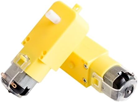
Can you explain the role of backlash in gear motors and how it’s managed in design?
Backlash plays a significant role in gear motors and is an important consideration in their design and operation. Backlash refers to the slight clearance or play between the teeth of gears in a gear system. It affects the precision, accuracy, and responsiveness of the gear motor. Here’s an explanation of the role of backlash in gear motors and how it is managed in design:
1. Role of Backlash:
Backlash in gear motors can have both positive and negative effects:
- Compensation for Misalignment: Backlash can help compensate for minor misalignments between gears, shafts, or the load. It allows a small amount of movement before engaging the next set of teeth, reducing the risk of damage due to misalignment. This can be particularly beneficial in applications where precise alignment is challenging or subject to variations.
- Negative Impact on Accuracy and Responsiveness: Backlash can introduce a delay or “dead zone” in the motion transmission. When changing the direction of rotation or reversing the load, the gear teeth must first overcome the clearance or play before engaging in the opposite direction. This delay can reduce the overall accuracy, responsiveness, and repeatability of the gear motor, especially in applications that require precise positioning or rapid changes in direction or speed.
2. Managing Backlash in Design:
Designers employ various techniques to manage and minimize backlash in gear motors:
- Tight Manufacturing Tolerances: Proper manufacturing techniques and tight tolerances can help minimize backlash. Precision machining and quality control during the production of gears and gear components ensure closer tolerances, reducing the amount of play between gear teeth.
- Preload or Pre-tensioning: Applying a preload or pre-tensioning force to the gear system can help reduce backlash. This technique involves introducing an initial force or tension that eliminates the clearance between gear teeth. It ensures immediate contact and engagement of the gear teeth, minimizing the dead zone and improving the overall responsiveness and accuracy of the gear motor.
- Anti-Backlash Gears: Anti-backlash gears are designed specifically to minimize or eliminate backlash. They typically feature modifications to the gear tooth profile, such as modified tooth shapes or special tooth arrangements, to reduce clearance. Anti-backlash gears can be used in gear motor designs to improve precision and minimize the effects of backlash.
- Backlash Compensation: In some cases, backlash compensation techniques can be employed. These techniques involve monitoring the position or movement of the load and applying control algorithms to compensate for the backlash. By accounting for the clearance and adjusting the control signals accordingly, the effects of backlash can be mitigated, improving accuracy and responsiveness.
3. Application-Specific Considerations:
The management of backlash in gear motors should be tailored to the specific application requirements:
- Positioning Accuracy: Applications that require precise positioning, such as robotics or CNC machines, may require tighter backlash control to ensure accurate and repeatable movements.
- Dynamic Response: Applications that involve rapid changes in direction or speed, such as high-speed automation or servo control systems, may require reduced backlash to maintain responsiveness and minimize overshoot or lag.
- Load Characteristics: The nature of the load and its impact on the gear system should be considered. Heavy loads or applications with significant inertial forces may require additional backlash management techniques to maintain stability and accuracy.
In summary, backlash in gear motors can affect precision, accuracy, and responsiveness. While it can compensate for misalignments, backlash may introduce delays and reduce the overall performance of the gear motor. Designers manage backlash through tight manufacturing tolerances, preload techniques, anti-backlash gears, and backlash compensation methods. The management of backlash depends on the specific application requirements, considering factors such as positioning accuracy, dynamic response, and load characteristics.
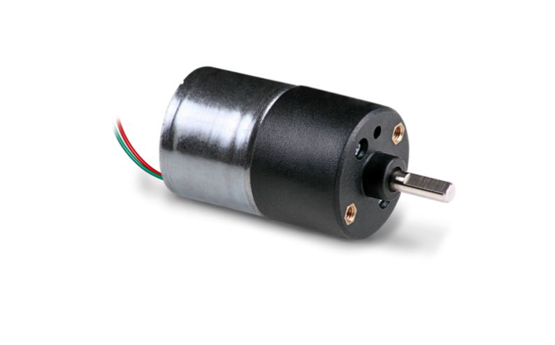
How does the gearing mechanism in a gear motor contribute to torque and speed control?
The gearing mechanism in a gear motor plays a crucial role in controlling torque and speed. By utilizing different gear ratios and configurations, the gearing mechanism allows for precise manipulation of these parameters. Here’s a detailed explanation of how the gearing mechanism contributes to torque and speed control in a gear motor:
The gearing mechanism consists of multiple gears with varying sizes, tooth configurations, and arrangements. Each gear in the system engages with another gear, creating a mechanical connection. When the motor rotates, it drives the rotation of the first gear, which then transfers the motion to subsequent gears, ultimately resulting in the output shaft’s rotation.
Torque Control:
The gearing mechanism in a gear motor enables torque control through the principle of mechanical advantage. The gear system utilizes gears with different numbers of teeth, known as gear ratio, to adjust the torque output. When a smaller gear (pinion) engages with a larger gear (gear), the pinion rotates faster than the gear but exerts more force or torque. This results in torque amplification, allowing the gear motor to deliver higher torque at the output shaft while reducing the rotational speed. Conversely, if a larger gear engages with a smaller gear, torque reduction occurs, resulting in higher rotational speed at the output shaft.
By selecting the appropriate gear ratio, the gearing mechanism effectively adjusts the torque output of the gear motor to match the requirements of the application. This torque control capability is essential in applications that demand high torque for heavy lifting or overcoming resistance, as well as applications that require lower torque but higher rotational speed.
Speed Control:
The gearing mechanism also contributes to speed control in a gear motor. The gear ratio determines the relationship between the rotational speed of the input shaft (driven by the motor) and the output shaft. When a gear motor has a higher gear ratio (more teeth on the driven gear compared to the driving gear), it reduces the output speed while increasing the torque. Conversely, a lower gear ratio increases the output speed while reducing the torque.
By choosing the appropriate gear ratio, the gearing mechanism allows for precise speed control in a gear motor. This is particularly useful in applications that require specific speed ranges or variations, such as conveyor systems, robotic movements, or machinery that needs to operate at different speeds for different tasks. The speed control capability of the gearing mechanism enables the gear motor to match the desired speed requirements of the application accurately.
In summary, the gearing mechanism in a gear motor contributes to torque and speed control by utilizing different gear ratios and configurations. It enables torque amplification or reduction, depending on the gear arrangement, allowing the gear motor to deliver the required torque output. Additionally, the gear ratio also determines the relationship between the rotational speed of the input and output shafts, providing precise speed control. These torque and speed control capabilities make gear motors versatile and suitable for a wide range of applications in various industries.


editor by CX 2024-05-10