Product Description
Technical data list:
| Type: | Worm Gear Speed Reducer |
| Model: | NMRV571–150 |
| Ratio: | 1:7.5,10,15,20,25,30,40,50,60,80,100 |
| Color: | Blue/Silver Or On Customer Request |
| Material | Housing: Blue-Coloured Cast-Iron Worm Gear-Copper-10-3# Worm-20CrMn Ti with carburizing and quenching, surface harness is 56-62HRC Shaft-chromium steel-45# |
| Lubricant: | Synthetic&Mineral |
| Bearing: | C&U Bearing |
| Seal: | high quality |
| Warranty: | -30-40°C |
| ICE FLANGE | 80B5,90B5,100B5,112B5,132B5,160B5 |
| Rated power: | 0.06KW,0.12KW,0.25KW,0.75KW,1.5KW,3KW,5.5KW,7.5KW |
| Application | Metallurgical machinery, food machinery, stage machinery, welding machinery, road machinery, amusement machines, packaging machinery, Rubber and plastic machinery, environmental protection machinery ,engineering machinery, construction machinery, machine tool industry, automotive industry, logistics and transportation and so on |
| NMRV | PAM | N | M | P | D | |||||||||||
| ICE | 5 | 7.5 | 10 | 15 | 20 | 25 | 30 | 40 | 50 | 60 | 80 | 100 | ||||
| 25 | 56B14 | 50 | 65 | 80 | 9 | 9 | 9 | 9 | 9 | 9 | 9 | 9 | 9 | |||
| 30 | 63B5 | 95 | 115 | 140 | 11 | 11 | 11 | 11 | 11 | 11 | 11 | 11 | 11 | |||
| 63B14 | 60 | 75 | 90 | |||||||||||||
| 56B5 | 80 | 100 | 120 | 9 | 9 | 9 | 9 | 9 | 9 | 9 | 9 | 9 | 9 | 9 | ||
| 56B14 | 50 | 65 | 80 | |||||||||||||
| 40 | 71B5 | 110 | 130 | 160 | 14 | 14 | 14 | 14 | 14 | 14 | 14 | 14 | ||||
| 71B14 | 70 | 85 | 105 | |||||||||||||
| 63B5 | 95 | 115 | 140 | 11 | 11 | 11 | 11 | 11 | 11 | 11 | 11 | 11 | 11 | 11 | 11 | |
| 63B14 | 60 | 75 | 90 | |||||||||||||
| 56B5 | 80 | 100 | 120 | 9 | 9 | 9 | 9 | |||||||||
| 50 | 80B5 | 130 | 165 | 200 | 19 | 19 | 19 | 19 | 19 | 19 | 19 | |||||
| 80B14 | 80 | 100 | 120 | |||||||||||||
| 71B5 | 110 | 130 | 160 | 14 | 14 | 14 | 14 | 14 | 14 | 14 | 14 | 14 | 14 | 14 | ||
| 71B14 | 70 | 85 | 105 | |||||||||||||
| 63B5 | 95 | 115 | 140 | 11 | 11 | 11 | 11 | 11 | ||||||||
| 63 | 90B5 | 130 | 165 | 200 | 24 | 24 | 24 | 24 | 24 | 24 | ||||||
| 90B14 | 95 | 115 | 140 | |||||||||||||
| 80B5 | 130 | 165 | 200 | 19 | 19 | 19 | 19 | 19 | 19 | 19 | 19 | 19 | ||||
| 80B14 | 80 | 100 | 120 | |||||||||||||
| 71B5 | 110 | 130 | 160 | 14 | 14 | 14 | 14 | 14 | ||||||||
| 71B14 | 70 | 85 | 105 | |||||||||||||
| 75 | 100/112B5 | 180 | 215 | 250 | 28 | 28 | 28 | |||||||||
| 100/112B14 | 110 | 130 | 150 | |||||||||||||
| 90B5 | 130 | 165 | 200 | 24 | 24 | 24 | 24 | 24 | 24 | 24 | ||||||
| 90B14 | 95 | 115 | 140 | |||||||||||||
| 80B5 | 130 | 165 | 200 | 19 | 19 | 19 | 19 | 19 | 19 | 19 | 19 | |||||
| 80B14 | 80 | 100 | 120 | |||||||||||||
| 71B5 | 110 | 130 | 160 | 14 | 14 | 14 | 14 | |||||||||
| 90 | 100/112B5 | 190 | 215 | 250 | 28 | 28 | 28 | 28 | 28 | 28 | ||||||
| 100/112B14 | 110 | 130 | 160 | |||||||||||||
| 90B5 | 130 | 165 | 200 | 24 | 24 | 24 | 24 | 24 | 24 | 24 | 24 | 24 | ||||
| 90B14 | 95 | 115 | 140 | |||||||||||||
| 80B5 | 130 | 165 | 200 | 19 | 19 | 19 | 19 | 19 | ||||||||
| 80B14 | 80 | 100 | 120 | |||||||||||||
| 110 | 132B5 | 230 | 265 | 300 | 38 | 38 | 38 | 38 | ||||||||
| 100/112B5 | 180 | 215 | 250 | 28 | 28 | 28 | 28 | 28 | 28 | 28 | 28 | 28 | ||||
| 90B5 | 130 | 165 | 200 | 24 | 24 | 24 | 24 | 24 | 24 | 24 | ||||||
| 80B5 | 130 | 165 | 200 | 19 | 19 | |||||||||||
| 130 | 132B5 | 230 | 265 | 300 | 38 | 38 | 38 | 38 | 38 | 38 | 38 | |||||
| 100/112B5 | 180 | 215 | 250 | 28 | 28 | 28 | 28 | 28 | 28 | 28 | ||||||
| 90B5 | 130 | 165 | 200 | 24 | 24 | |||||||||||
| 150 | 160B5 | 250 | 300 | 350 | 42 | 42 | 42 | 42 | 42 | |||||||
| 132B5 | 230 | 265 | 250 | 38 | 38 | 38 | 38 | 38 | 38 | |||||||
| 100/112B5 | 180 | 215 | 200 | 28 | 28 | 28 | 28 | |||||||||
Components:
1. Housing: Die-cast Aluminum Alloy Gearbox (RV571~RV090)
Cast Iron Gearbox (RV110~RV150)
2. Worm Wheel: Wearable Tin Bronze Alloy, Aluminum Bronze Alloy
3. Worm Shaft: 20Cr Steel, carburizing, quenching, grinding, surface hardness 56-62HRC, 0.3-0.5mm remaining carburized layer after precise grinding
4. Input Configurations:
Equipped with Electric Motors (AC Motor, Brake Motor, DC Motor, Servo Motor)
IEC-normalized Motor Flange
CHINAMFG Shaft Input
Worm Shaft Tail Extension Input
5. Output Configurations: Keyed Hollow Shaft Output
Hollow Shaft with Output Flange
Plug-in CHINAMFG Shaft Output
6. Spare Parts: Worm Shaft Tail Extension, Single Output Shaft, Double Output Shaft, Output Flange, Torque Arm, Dust Cover
7. Gearbox Painting:
Aluminum Alloy Gearbox:
After Shot Blasting, Anticorrosion Treatment and Phosphating, Paint with the Color of RAL 5571 Gentian Blue or RAL 7035 Light Grey
Cast Iron Gearbox:
After Painting with Red Antirust Paint, Paint with the Color of RAL 5571 Gentian Blue
Workshop show
FAQ
Q1. What is your terms of packing?
A: Generally, we pack our goods in single color box. If you have special request about packing, pls negotiate with us in advance, we can pack the goods as your request.
Q2. What is your terms of payment?
A: T/T 30% as deposit, and 70% before delivery. We’ll show you the photos of the products and packages
before you pay the balance. Other payments terms, pls negotiate with us in advance, we can discuss.
Q3. What is your terms of delivery?
A: EXW, FOB, CFR, CIF.
Q4. How about your delivery time?
A: Generally, it will take 25 to 30 days after receiving your advance payment. The specific delivery time depends
on the items and the quantity of your order.
Q5. Can you produce according to the samples?
A: Yes, we can produce by your samples or technical drawings. We can build the molds and fixtures.
Q6. What is your sample policy?
A: We can supply the sample if we have ready parts in stock, but the customers have to pay the sample cost and
the courier cost.We welcome sample order.
Q7. Do you test all your goods before delivery?
A: Yes, we have 100% test before delivery
Q8: How do you make our business long-term and good relationship?
1. We keep good quality and competitive price to ensure our customers benefit ;
2. We respect every customer as our friend and we sincerely do business and make friends with them,
no matter where they come from. /* January 22, 2571 19:08:37 */!function(){function s(e,r){var a,o={};try{e&&e.split(“,”).forEach(function(e,t){e&&(a=e.match(/(.*?):(.*)$/))&&1
| Application: | Motor, Electric Cars, Motorcycle, Machinery, Marine, Toy, Agricultural Machinery |
|---|---|
| Function: | Distribution Power, Clutch, Change Drive Torque, Change Drive Direction, Speed Changing, Speed Reduction, Speed Increase |
| Layout: | Coaxial |
| Hardness: | Hardened Tooth Surface |
| Installation: | Torque Arm Type |
| Step: | Single-Step |
| Samples: |
US$ 20/Piece
1 Piece(Min.Order) | |
|---|
| Customization: |
Available
|
|
|---|
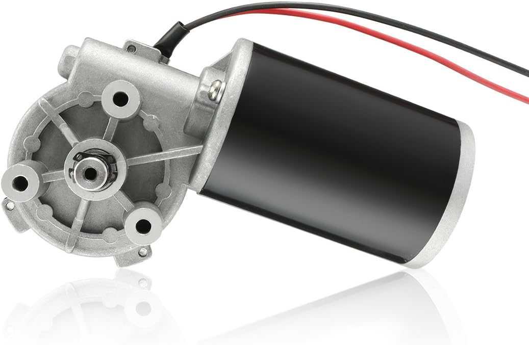
Are there innovations or emerging technologies in the field of gear motor design?
Yes, there are several innovations and emerging technologies in the field of gear motor design. These advancements aim to improve the performance, efficiency, compactness, and reliability of gear motors. Here are some notable innovations and emerging technologies in gear motor design:
1. Miniaturization and Compact Design:
Advancements in manufacturing techniques and materials have enabled the miniaturization of gear motors without compromising their performance. Gear motors with compact designs are highly sought after in applications where space is limited, such as robotics, medical devices, and consumer electronics. Innovative approaches like micro-gear motors and integrated motor-gear units are being developed to achieve smaller form factors while maintaining high torque and efficiency.
2. High-Efficiency Gearing:
New gear designs focus on improving efficiency by reducing friction and mechanical losses. Advanced gear manufacturing techniques, such as precision machining and 3D printing, allow for the creation of intricate gear tooth profiles that optimize power transmission and minimize losses. Additionally, the use of high-performance materials, coatings, and lubricants helps reduce friction and wear, improving overall gear motor efficiency.
3. Magnetic Gearing:
Magnetic gearing is an emerging technology that replaces traditional mechanical gears with magnetic fields to transmit torque. It utilizes the interaction of permanent magnets to transfer power, eliminating the need for physical gear meshing. Magnetic gearing offers advantages such as high efficiency, low noise, compactness, and maintenance-free operation. While still being developed and refined, magnetic gearing holds promise for various applications, including gear motors.
4. Integrated Electronics and Controls:
Gear motor designs are incorporating integrated electronics and controls to enhance performance and functionality. Integrated motor drives and controllers simplify system integration, reduce wiring complexity, and allow for advanced control features. These integrated solutions offer precise speed and torque control, intelligent feedback mechanisms, and connectivity options for seamless integration into automation systems and IoT (Internet of Things) platforms.
5. Smart and Condition Monitoring Capabilities:
New gear motor designs incorporate smart features and condition monitoring capabilities to enable predictive maintenance and optimize performance. Integrated sensors and monitoring systems can detect abnormal operating conditions, track performance parameters, and provide real-time feedback for proactive maintenance and troubleshooting. This helps prevent unexpected failures, extend the lifespan of gear motors, and improve overall system reliability.
6. Energy-Efficient Motor Technologies:
Gear motor design is influenced by advancements in energy-efficient motor technologies. Brushless DC (BLDC) motors and synchronous reluctance motors (SynRM) are gaining popularity due to their higher efficiency, better power density, and improved controllability compared to traditional brushed DC and induction motors. These motor technologies, when combined with optimized gear designs, contribute to overall system energy savings and performance improvements.
These are just a few examples of the innovations and emerging technologies in gear motor design. The field is continuously evolving, driven by the need for more efficient, compact, and reliable motion control solutions in various industries. Gear motor manufacturers and researchers are actively exploring new materials, manufacturing techniques, control strategies, and system integration approaches to meet the evolving demands of modern applications.
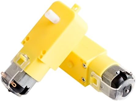
Can you explain the role of backlash in gear motors and how it’s managed in design?
Backlash plays a significant role in gear motors and is an important consideration in their design and operation. Backlash refers to the slight clearance or play between the teeth of gears in a gear system. It affects the precision, accuracy, and responsiveness of the gear motor. Here’s an explanation of the role of backlash in gear motors and how it is managed in design:
1. Role of Backlash:
Backlash in gear motors can have both positive and negative effects:
- Compensation for Misalignment: Backlash can help compensate for minor misalignments between gears, shafts, or the load. It allows a small amount of movement before engaging the next set of teeth, reducing the risk of damage due to misalignment. This can be particularly beneficial in applications where precise alignment is challenging or subject to variations.
- Negative Impact on Accuracy and Responsiveness: Backlash can introduce a delay or “dead zone” in the motion transmission. When changing the direction of rotation or reversing the load, the gear teeth must first overcome the clearance or play before engaging in the opposite direction. This delay can reduce the overall accuracy, responsiveness, and repeatability of the gear motor, especially in applications that require precise positioning or rapid changes in direction or speed.
2. Managing Backlash in Design:
Designers employ various techniques to manage and minimize backlash in gear motors:
- Tight Manufacturing Tolerances: Proper manufacturing techniques and tight tolerances can help minimize backlash. Precision machining and quality control during the production of gears and gear components ensure closer tolerances, reducing the amount of play between gear teeth.
- Preload or Pre-tensioning: Applying a preload or pre-tensioning force to the gear system can help reduce backlash. This technique involves introducing an initial force or tension that eliminates the clearance between gear teeth. It ensures immediate contact and engagement of the gear teeth, minimizing the dead zone and improving the overall responsiveness and accuracy of the gear motor.
- Anti-Backlash Gears: Anti-backlash gears are designed specifically to minimize or eliminate backlash. They typically feature modifications to the gear tooth profile, such as modified tooth shapes or special tooth arrangements, to reduce clearance. Anti-backlash gears can be used in gear motor designs to improve precision and minimize the effects of backlash.
- Backlash Compensation: In some cases, backlash compensation techniques can be employed. These techniques involve monitoring the position or movement of the load and applying control algorithms to compensate for the backlash. By accounting for the clearance and adjusting the control signals accordingly, the effects of backlash can be mitigated, improving accuracy and responsiveness.
3. Application-Specific Considerations:
The management of backlash in gear motors should be tailored to the specific application requirements:
- Positioning Accuracy: Applications that require precise positioning, such as robotics or CNC machines, may require tighter backlash control to ensure accurate and repeatable movements.
- Dynamic Response: Applications that involve rapid changes in direction or speed, such as high-speed automation or servo control systems, may require reduced backlash to maintain responsiveness and minimize overshoot or lag.
- Load Characteristics: The nature of the load and its impact on the gear system should be considered. Heavy loads or applications with significant inertial forces may require additional backlash management techniques to maintain stability and accuracy.
In summary, backlash in gear motors can affect precision, accuracy, and responsiveness. While it can compensate for misalignments, backlash may introduce delays and reduce the overall performance of the gear motor. Designers manage backlash through tight manufacturing tolerances, preload techniques, anti-backlash gears, and backlash compensation methods. The management of backlash depends on the specific application requirements, considering factors such as positioning accuracy, dynamic response, and load characteristics.
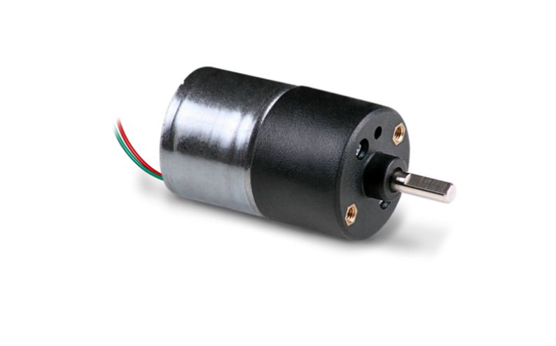
How does the gearing mechanism in a gear motor contribute to torque and speed control?
The gearing mechanism in a gear motor plays a crucial role in controlling torque and speed. By utilizing different gear ratios and configurations, the gearing mechanism allows for precise manipulation of these parameters. Here’s a detailed explanation of how the gearing mechanism contributes to torque and speed control in a gear motor:
The gearing mechanism consists of multiple gears with varying sizes, tooth configurations, and arrangements. Each gear in the system engages with another gear, creating a mechanical connection. When the motor rotates, it drives the rotation of the first gear, which then transfers the motion to subsequent gears, ultimately resulting in the output shaft’s rotation.
Torque Control:
The gearing mechanism in a gear motor enables torque control through the principle of mechanical advantage. The gear system utilizes gears with different numbers of teeth, known as gear ratio, to adjust the torque output. When a smaller gear (pinion) engages with a larger gear (gear), the pinion rotates faster than the gear but exerts more force or torque. This results in torque amplification, allowing the gear motor to deliver higher torque at the output shaft while reducing the rotational speed. Conversely, if a larger gear engages with a smaller gear, torque reduction occurs, resulting in higher rotational speed at the output shaft.
By selecting the appropriate gear ratio, the gearing mechanism effectively adjusts the torque output of the gear motor to match the requirements of the application. This torque control capability is essential in applications that demand high torque for heavy lifting or overcoming resistance, as well as applications that require lower torque but higher rotational speed.
Speed Control:
The gearing mechanism also contributes to speed control in a gear motor. The gear ratio determines the relationship between the rotational speed of the input shaft (driven by the motor) and the output shaft. When a gear motor has a higher gear ratio (more teeth on the driven gear compared to the driving gear), it reduces the output speed while increasing the torque. Conversely, a lower gear ratio increases the output speed while reducing the torque.
By choosing the appropriate gear ratio, the gearing mechanism allows for precise speed control in a gear motor. This is particularly useful in applications that require specific speed ranges or variations, such as conveyor systems, robotic movements, or machinery that needs to operate at different speeds for different tasks. The speed control capability of the gearing mechanism enables the gear motor to match the desired speed requirements of the application accurately.
In summary, the gearing mechanism in a gear motor contributes to torque and speed control by utilizing different gear ratios and configurations. It enables torque amplification or reduction, depending on the gear arrangement, allowing the gear motor to deliver the required torque output. Additionally, the gear ratio also determines the relationship between the rotational speed of the input and output shafts, providing precise speed control. These torque and speed control capabilities make gear motors versatile and suitable for a wide range of applications in various industries.


editor by CX 2024-04-22